Two Pipe Change Over

Two Pipe Change Over
Two pipe change over (TPCO) systems are typically used where it is too expensive to run dual sets of pipe work to each consumer, or it is expected that there will be a low number of days the units actually spend heating. With a single set of pipes, the unit can only heat or cool at one time.
Ordinarily, it is expected for the space to have some form of backup heating (typically electric elements), to use when the system is in cooling and only when a few zones require heating.
TPCO systems are usable for:
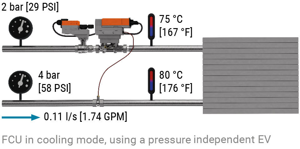
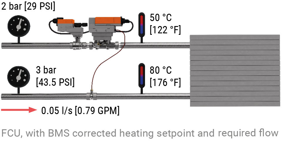
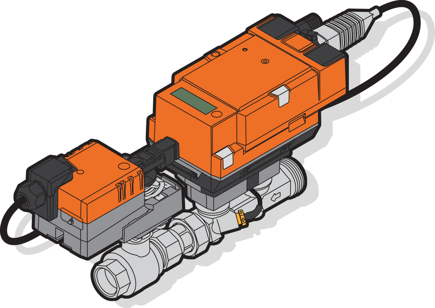
The figure shows a condensed setup with a single terminal unit. However, applying EVs instead of standard control valves uniquely allows designers to use the less costly two pipe design, while still achieving the same comfort associated with four pipe systems. Energy Valves can be updated with different flow and delta T setpoints for cooling and heating, in effect, the BMS is able to make the same valve act like two different valves.
Problem: Pressure fluctuations affecting flow rates and comfort
Large chilled water systems are dynamic in nature, with pressure fluctuations caused by pump speed and valve position changes. Statically balanced systems, as the name suggests, are unable to deal with these dynamic changes and, as a result, flow rates through each unit fluctuates with pressure changes.
Possible Solution: Dynamic balancing
The dynamic balancing function of a pressure independent valve handles pressure fluctuations in the system, and assures that the flow is maintained on the defined setpoint.
Learn how the Energy Valve improves your two pipe change over system
Heat exchangers or coils are typically selected on cooling loads, meaning that if the water medium is simply switched from cold to warm, the design flow rates are no longer suitable. For example, a typical cooling delta T would be 7 K, while you would expect a heating delta T of at least twice that.
As an intelligent valve is capable of high level communication with the BMS, flow rates can be updated remotely. This allows a change in design flow rates to be applied so that the valve is always controlling to the optimum flow rate.
As the heat exchanger is not only experiencing a change in water temperature, it could be experiencing a change in air volume in line with the new mode. With multiple variables of the heat exchange fluctuating, it now becomes virtually impossible to completely predict the correct flow rate over the range of permitted flows.
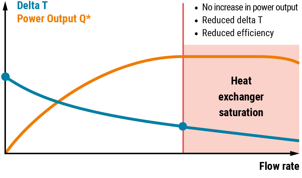
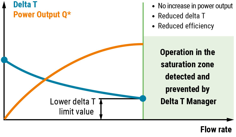
The Delta T Manager, integrated in the Belimo Energy Valve™, is a function that continuously measures the temperature spread and compares it with the systemspecific limiting value. If it falls below this, the Belimo Energy Valve™ automatically adjusts the flow so that only the amount of water actually needed is allowed through the heat exchanger. It is possible to update the required delta T using the bus interface, as easily as the water flows, giving you complete control.
The Energy Valve will also record the usage of heating and cooling energy separately, so instead of buying two meters, one for heating and one for cooling, now you only need one device!
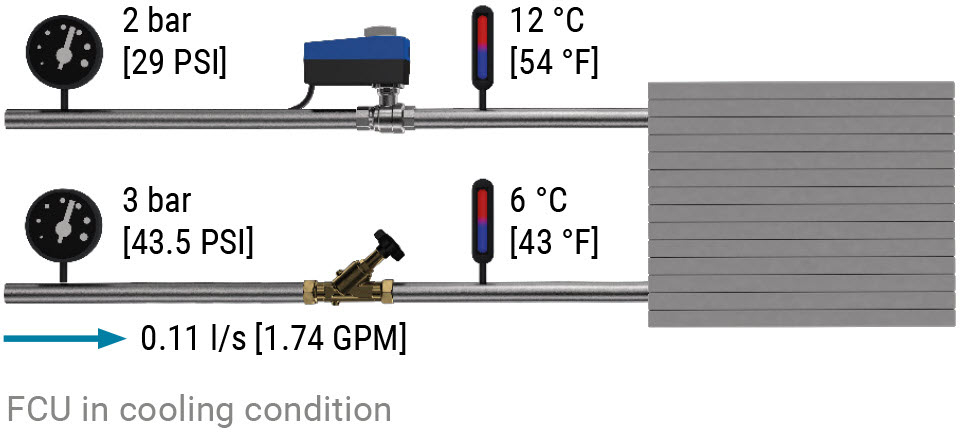
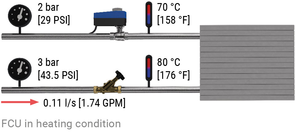
The example shown in the figure depicts a traditional setup with a flow rate of 0.11 l/s [1.74 GPM], based on the required cooling power, given inlet temperatures 6 °C [43 °F] and outlet temperature 12 °C [54 °F]. The heating flow rate required for the space is 0.05 l/s [0.79 GPM]. However, the system is set to deliver 0.11 l/s [1.74 GPM]. As a result, the heating performance is largely on/off.
This works to a degree, but the poor delta T experienced during the heating phase typically makes this setup incompatible with condensing boilers, because the return temperatures are too high for them to condense. As the heat exchanger is given the same fl ow rate of 0.11 l/s [1.74 GPM] when heating, the water is unable to give up sufficient energy to air, resulting in high return water temperatures or low delta T, as shown in fi gure 106.
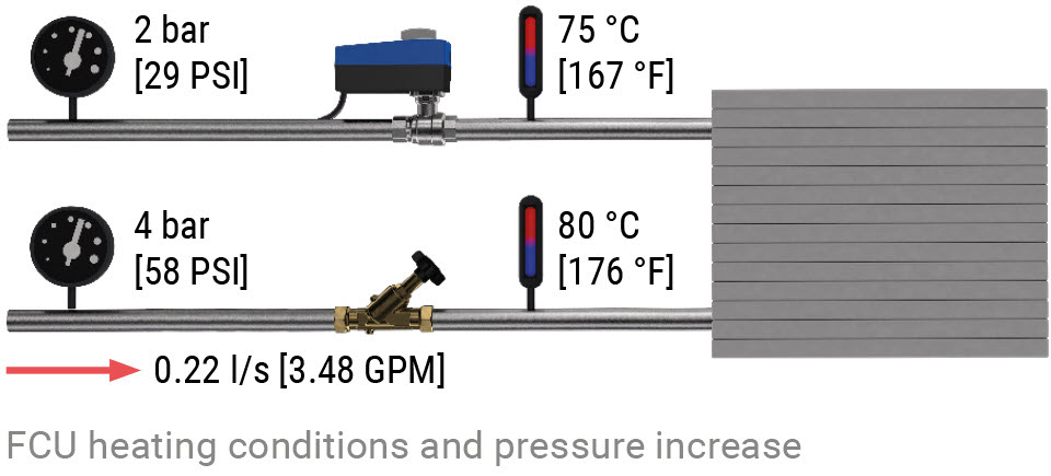
As there are no PI valves fi tted to this solution, we still suffer with all the cross pressure fl uctuations typically seen with non-PI valve setups. This worsens the delta T further.
With the Energy Valve being updated with heating flow rates and delta T, the valve switches to 0.05 l/s [0.79 GPM] and enforces a minimum delta T of 30 K. Doing so, now allows the use of condensing boilers on the project, as the return water temperatures can be assured.
